 . This will open up the detail report window.
 button that will open up the detail report window when you click on a particular Design Strip.
This topic is specific to design strip detail report results.
Note
The detail report gives detailed information about the design strip. Here we will walk through how to access the analytical and design information for the Design Strips.
Note:
Once you have a solved model, the detail reports become available. They are accessible in two ways:
. This will open up the detail report window. button that will open up the detail report window when you click on a particular Design Strip.Once the detail report window is open, you will see a dialog area at the top.
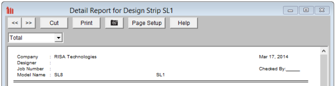
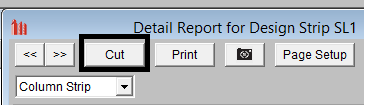
 - Allows you to click between the different design strips in your model.
 - This button will allow you to take a snapshot of the current detail report you are viewing so that it can be added to a report. View the Printing topic for more information.
 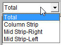 - This dropdown list allows you to select between the total design strip results or the three different design region results. Below we will explain the importance of each of these sections.
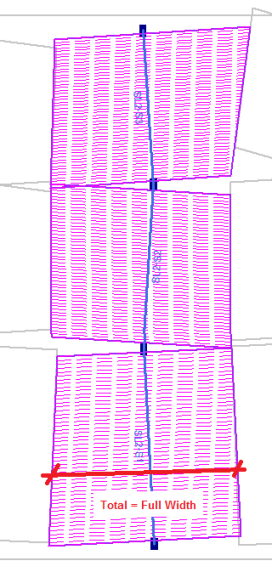
The Total Design Strip report gives an overall summary of the full width of the design strip. The Total Design Strip will only give analysis information (not design/reinforcement information). The picture below illustrates the Design Cut across the Total Design Strip (at only one span for simplicity).
Input Echo
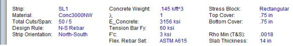
This lists information about the total design strip details. Below is the input echo portion of the detail report.
| Criteria | Description |
|---|---|
| Strip | Slab Design Strip Label defined in the Slab Design Strips spreadsheet |
| Material |
Slab Material defined in the Slab Definitions spreadsheet |
| Total Cuts/Span | Number of Design Cuts defined in the Slab Design Strips spreadsheet/Number of spans per support line |
| Design Rule | Design strip Design Rule defined in the Slab Design Strips spreadsheet |
| Strip Orientation | N-S or E-W defined in the Slab Design Strip Spreadsheet |
| Concrete Weight | Slab weight defined in the Slab Definitions spreadsheet |
| Lamda | Lightweight concrete modification factor defined in the Concrete Materials spreadsheet |
| E_Concrete | Elastic modulus defined in the Concrete Materials spreadsheet |
| Tension Bar Fy | Strength of Bar in tension defined in the Materials spreadsheet- Concrete tab- Flex Steel |
| F'c | Concrete Yield Stress from Material spreadsheet |
| Flex. Rebar Set | The Concrete Rebar Set is selected in the Global Paremeters- Concrete tab. The Standard ASTM A615 (imperial), ASTM A1064 (imperial) and ASTM A615M (metric) are supported. |
| Stress Block | Stress Block from the Model Settings- Concrete tab. Only Rectangular is supported. |
| Top Cover | Clear cover from the top bar to the top of slab |
| Bottom Cover | Clear cover from the bottom bar to the bottom of the slab |
| Rho Min (T&S) | The ratio of reinforcement corresponding the area of steel to bd |
| Slab Thickness | Overall thickness of the slab defined in the Slab Definitions spreadsheet. |
Diagrams
The Shear and Moment diagrams display the Envelope result based on the Load Combinations checked. The program assumes that your spans start and end at a support. The supports are represented in the diagrams as gaps. The column strip and Mid-strip detail reports will show the support labels in the Rebar Detailed Drawing for reference. The minimum and maximum values are listed at the bottom for the entire support line.
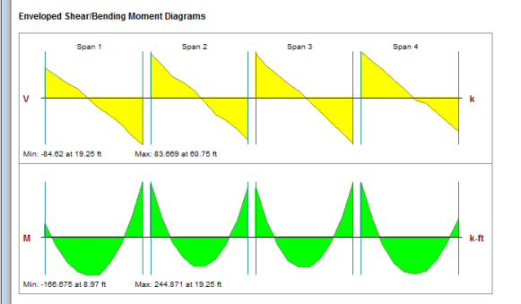
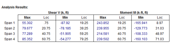
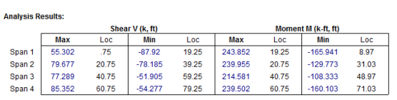
This portion gives the detailed information of the diagrams above displaying the minimum and maximum shear and moment in each span, along with the controlling location.
These deflections are based on the Total Design Strip width along the Support Line Spans. The program also reports this value in the Slab Strip Deflections spreadsheet. The Slab Strip Deflection is based on the Load Categories (not Load Combinations). Each Support Line has a Slab Design Rule which defines the Deflection criteria. The program finds the actual deflection and compares it to the limits defined in the Slab Design Rule to calculate the ratio.
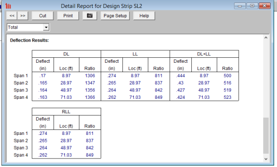
The program checks each span separately, and within those spans each Design Cut is checked to find the maximum deflection.
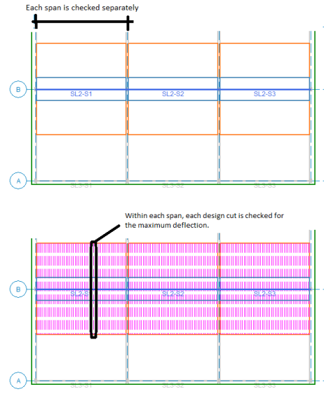
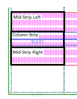
The Column Design Strip, Mid-Strip Right and Mid-Strip Left Detail Report gives the summary of the all the cuts within that strip. The picture below illustrates the Design Cuts (pink dashed lines) across the strip (at only one span for simplicity).
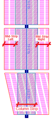
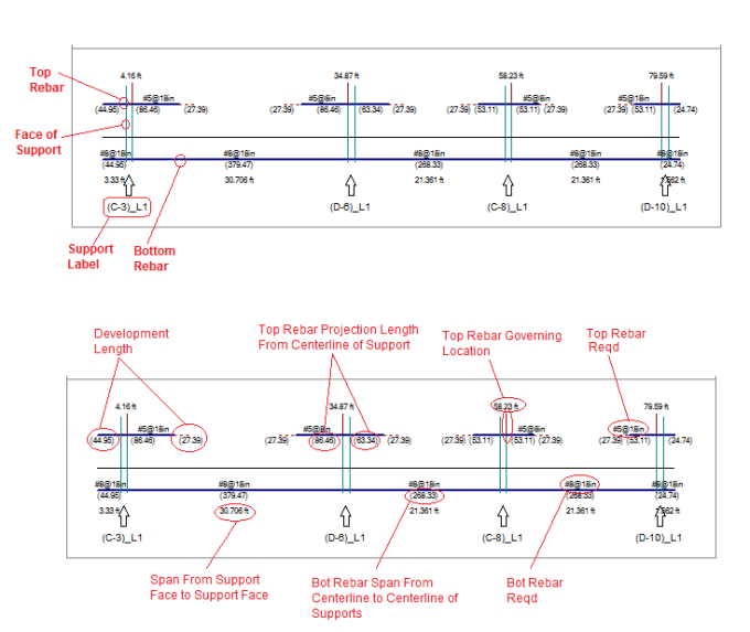
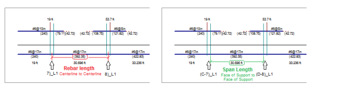
The Column Strip and Mid-Strip Detail Reports have reinforcement design. The Rebar Detailed Drawing is directly in-line with the Moment diagrams so that you can see the analytical demand. Below shows a picture describing all of the labels and symbols on the drawing.
Note:
This portion gives the detailed information of the diagrams above displaying the minimum and maximum in each span and the controlling location. The location is the overall location in relation to the Support Line.
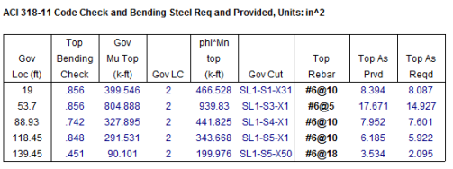
The first table describes the positive moment demand and the top reinforcement.
| Criteria | Description |
|---|---|
| Gov Loc | This gives the overall location along the span that yielded the worst case design cut for top reinforcement design. See below for more information. |
| Top Bending Check | This is a calculated code check based on the top reinforcement design capacity vs. moment demand. |
| Gov Mu Top |
This is the largest moment demand in this segment. The top reinforcement spacing must be equal on both sides of a support so this governing positive moment could be from the left or right of the support. See Gov Loc for the actual location. |
| Gov LC | This is the governing Load Combination for the top reinforcement. |
| phi*Mn top | This is the capacity based on the amount of top reinforcement. |
| Gov Cut | This is the governing Design Cut that controls the design for the top reinforcement. |
| Top Rebar | Size and spacing of flexural reinforcement at the top of the slab. If welded wire bars are designed, the output result will be preceded by a “D” instead of “#” to indicate wire bar size. |
| Top As Prvd | Area of Steel provided in the top of the slab |
| Top As Reqd | Area of Steel required in the top of the slab |
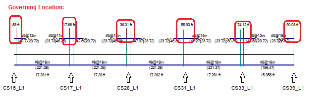
Governing Location- This gives the overall location along the span that yielded the worst case design cut. This table is organized by the governing location because at each support point there will be one governing location that controls the design. The top reinforcement is required to be the same spacing at each side of support point.
This governing location is also displayed on the Rebar Detailed Drawing with a red "tick" mark and the dimension listed.
The second table describes the negative (mid-span) moment demand and the bottom reinforcement. This table is span based since the bottom reinforcement is designed span by span.
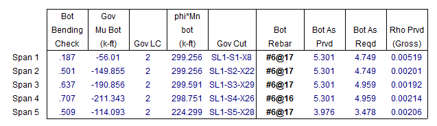
| Criteria | Description |
|---|---|
| Bot Bending Check | This is a calculated code check based on the bottom reinforcement design capacity vs. moment demand. |
| Gov Mu Bot |
This is the largest negative moment demand in the span. |
| Gov LC | This is the governing Load Combination for the bottom reinforcement. |
| phi*Mn bot | This is the capacity based on the amount of bottom reinforcement. |
| Gov Cut | This is the governing Design Cut that controls the design of the bottom reinforcement. |
| Bot Rebar | Size and spacing of flexural reinforcement at the bottom of the slab. If welded wire bars are designed, the output result will be preceded by a “D” instead of “#” to indicate wire bar size. |
| Bot As Prvd | Area of Steel provided in the bottom of the slab |
| Bot As Reqd | Area of Steel required in the bottom of the slab |
| Rho Prvd(Gross) | The ratio of reinforcement corresponding the area of steel (entire slab) to bd |
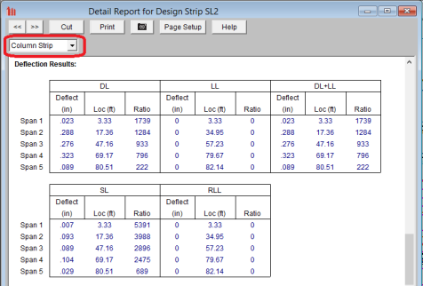
The Total Design Strip is broken into 3 regions: Column Strip, Mid-Strip Left and Mid-Strip Right. The Detail Report gives more information on the deflection by reporting the maximums in each of these regions.
The Slab Strip Deflection is based on the Load Categories (not Load Combinations). Each Support Line has a Slab Design Rule which defines the Deflection criteria. The program finds the actual deflection and compares it to the limits defined in the Slab Design Rule.
Similar to the detail report for Design Strips, you have the ability to view the detail report for a Design Cut. Each Design Strip is made up of multiple Design Cuts. The Design Cuts reports are given for each cut in the Design Strip and allow you to get detailed calculation information.
Note:
Once you have a solved model, the Design Cut detail reports become available. They are accessible in two ways:
 button that will open up the detail report window when you click on a Design Cut.
Once the detail report window is open, you will see a dialog area at the top.
- Allows you to toggle between the different Design Cuts in your model.
- This button will allow you to take a snapshot of the current detail report you are viewing so that it can be added to a report. View the Printing topic for more information.There are drop-down menus to help navigate between design regions, spans and cuts.
Input Echo
This lists information about the Design Cut details. Below is the input echo portion of the detail report.
| Criteria | Description |
|---|---|
| Cut | Slab Design Cut Label automatically generated within each Design Strip |
| Material |
Slab Material defined in the Slab Definitions spreadsheet |
| Start | Point Location defining the start of the Design Cut |
| End | Point Location defining the end of the Design Cut |
| Max Top bar Spac | Maximum Top Rebar Spacing defined in the Slab Design Rules spreadsheet |
| Min Top bar Spac | Minimum Top Rebar Spacing defined in the Slab Design Rules spreadsheet |
| Max Bot bar Spac | Maximum Bottom Rebar Spacing defined in the Slab Design Rules spreadsheet |
| Min Bot bar Spac | Minimum Bottom Rebar Spacing defined in the Slab Design Rules spreadsheet |
| Stress Block | Stress block used in the analysis defined in Model Settings |
| Slab Design Option | Slab Design Option used in the rebar design defined in Model Setting |
| Rebar Spacing Inc | The increment of bar spacing the program will try during the iteration of design |
| Design Rule | Design Rule defined in Slab Design Rules spreadsheet |
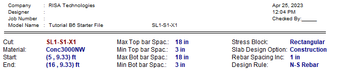
The Total Design Cut contains only analysis results in the Design Cut detail report. Since the Design Strip reinforcement design is based on the Design region (Column Strip, Middle Strip) this Detail Report does not show any reinforcement. It is a useful to present the summation of forces in the entire Design Cut. Listed below are the available controlling values along the total length of the Design Cut.
| Criteria | Description |
|---|---|
| Gov Mu Top | Governing maximum positive moment value |
| Gov Mu Bottom |
Governing maximum negative moment value |
|
Gov Vu |
Governing maximum shear value |
| Max Deflection |
Maximum deflection anywhere along Total Design Cut |
| Gov Category | The governing categories defined in the Slab Design Rules- Deflection tab. This in not LC based rather Load Category based. See the Deflection Calculations section for further information. |
| Criteria | Description |
|---|---|
| Top Bending Check | This is a calculated code check based on the top reinforcement design capacity vs. moment demand. |
| Gov Mu Top |
Total positive moment along the cut. (CSA A23.3-14 uses Mf) |
| phi*Mn Top | This is the capacity based on the amount of top reinforcement. (CSA A23.3-14 uses Mr) |
| Bot Bending Check | This is a calculated code check based on the bottom reinforcement design capacity vs. moment demand. |
| Gov Mu Bottom |
Total negative moment along the cut. (CSA A23.3-14 uses Mf) |
| phi*Mn Bot | This is the capacity based on the amount of bottom reinforcement. (CSA A23.3-14 uses Mr) |
| 1 Way Shear Check | This is a calculated code check based on the shear capacity of the concrete slab v shear demand. |
|
Gov Vu |
Total shear along the cut. (CSA A23.3-14 uses Vf) |
| phi*Vn | Shear capacity of the concrete slab. (CSA A23.3-14 uses Vr) |
| Strain(ey) | CSA A23.3-14 longitudinal strain calculated per the General Method in section 11.3.6.4 |
| Tension Bar Fy | Minimum yield stress of tension reinforcement. |
| F'c | Concrete compressive strength defined in the Slab Definitions spreadsheet. |
| Flex. Rebar Set | Flexural Rebar Set defined in the Model Settings- Concrete tab. |
| Concrete Weight | Slab weight defined in the Slab Definitions spreadsheet. |
| Lamda | Lightweight concrete modification factor defined in the Concrete Materials spreadsheet. |
| E_Concrete |
Elastic modulus defined in the Concrete Materials spreadsheet. |
| Top Cover | Distance from top slab edge to top reinforcement defined in the Slab Design Rules Spreadsheet. |
| Bottom Cover | Distance from bottom slab edge to bottom reinforcement defined in the Slab Design Rules Spreadsheet. |
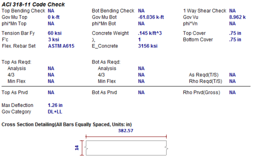
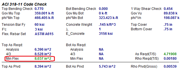
The program calculates the area steel required based on the steps listed below. The green text indicates the number that governed for that Design Cut.
Step 1 (Analysis): Calculate the area steel required by analysis. Select a spacing and number of bars that fit the design region.
Step 2 (Min Flex): Check that the minimum reinforcement for flexure is being met per ACI 318-14 Section 9.6.1 (ACI 318-11 Section 10.5, CSA A23.3-14 Section 10.5.1.2).
Step 3 (4/3): Check the 4/3*As required by analysis per ACI 318-11 Section 10.5.3, CSA A23.3-14 Section 10.5.1.3.
Note: ACI 2014 does not use the 4/3 As for slabs, the results will show NA.
In the example shown below, the green text indicates that the Top Area of Steel Provided met the Analysis requirements and was increased to meet the Minimum Flexural requirements. Since the 4/3 was greater than Min Flex, it was not used.
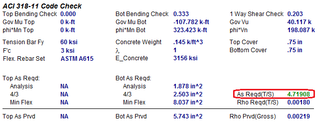
The bottom reinforcement design is the same as listed above except the temperature and shrinkage requirements are also checked. The bottom reinforcement must be uniform across the entire span but the top reinforcement will stop and start over supports. Therefore the mid-span cuts where there is only bottom reinforcement will always govern for temperature and shrinkage. Below shows an example where the As required is being governed by Temperature and Shrinkage.
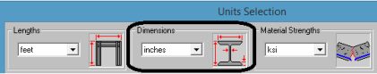
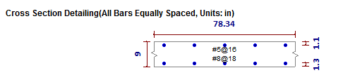
Depending on the Slab Design Option users selected in Global Model Setting - Concrete tab, the Cross Section Detailing can be different.
If the Construction Method is selected, the cross section will show the actual rebar amount:
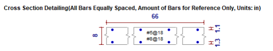
If the Theoretical Method is selected, the cross section will show a generic view and the rebar displayed are for reference only. We do not show the rebar amount because the rebar calculation is based on average rebar area and the rebar amount may not be an integer:
Similar to the detail report for Design Strips, you have the ability to view the detail report for a manual Design Cut. You will not receive design information for this option but will be able to view analysis results including governing moment and shear magnitudes.
Note:
Once you have a solved model, the Design Cut detail reports become available. They are accessible in two ways:
. This will open up the detail report window. button that will open up the detail report window when you click on a Design Cut.Once the detail report window is open, you will see a dialog area at the top.
- Allows you to toggle between the different Design Cuts in your model.- This button will allow you to take a snapshot of the current detail report you are viewing so that it can be added to a report. View thePrintingtopic for more information.Input Echo
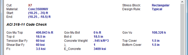
This lists information about the Design Cut details. Below is the input echo portion of the detail report.
| Criteria | Description |
|---|---|
| Cut | Slab Design Cut Label defined in the Slab Design Strips spreadsheet under the Cuts tab |
| Material |
Slab Material defined in the Slab Definitions spreadsheet |
| Start | Point Location defining the start of the Design Cut |
| End | Point Location defining the end of the Design Cut |
| Stress Block | Stress block used in the analysis defined in Model Settings |
| Design Rule | Design Rule defined in Slab Design Rules spreadsheet |
| Top d | Slab thickness minus top cover |
| Bot d | Slab thickness minus bottom cover |
| Tension Bar Fy | Minimum yield stress of tension reinforcement |
| F'c | Concrete compressive strength defined in the Slab Definitions spreadsheet |
| Concrete Weight | Slab weight defined in the Slab Definitions spreadsheet |
| Lamda | Lightweight concrete modification factor defined in the Concrete Materials spreadsheet |
| E_Concrete |
Elastic modulus defined in the Concrete Materials spreadsheet |
| Top Cover | Distance from top slab edge to top reinforcement defined in the Slab Design Rules Spreadsheet |
| Bottom Cover | Distance from bottom slab edge to bottom reinforcement defined in the Slab Design Rules Spreadsheet |
The analysis results are included the Design Cut detail report. Listed below are the available controlling values along the total length of the Design Cut.
| Criteria | Description |
|---|---|
| Gov Mu Top | Total positive moment along the cut. |
| Gov Mu Bottom |
Total negative moment along the cut. |
| Gov Vu | Total shear along the cut. |
These values are also available in the Slab Results/Rebar spreadsheet after an analysis is ran. See Elevated Slabs - Spreadsheet Results for more information.